Electric vehicle adoption is reshaping parking lot design, not merely replacing fuel pumps. The International Energy Agency’s Global EV Outlook 2025 reports that worldwide electric car sales exceeded 17 million in 2024. Electric vehicles represented more than 20% of new-car sales. This momentum makes reliable destination charging a practical business asset. It also exposes weak planning quickly. Drivers notice blocked spaces, short cables, poor lighting, and confusing payment instructions.
This 2026 guide examines how to install an ev charger pedestal in a parking lot with safety, access, and long-term performance in mind. The U.S. Department of Energy’s Alternative Fuels Data Center emphasizes site assessment, electrical capacity, network connectivity, and charger placement. A professional installation begins with a load calculation, utility consultation, drainage review, and clear traffic-path analysis. The ground decides. Concrete thickness, reinforcing steel, soil conditions, and trench routes can change the budget significantly. A pedestal may look simple, yet its foundation carries physical impact risks and weather exposure.
Industry guidance, including the National Electrical Code and accessibility standards, should be verified with qualified local professionals and authorities. Requirements can differ by location and property type. A certified electrician should confirm conductor sizing, overcurrent protection, grounding, disconnect access, and commissioning tests. The U.S. National Renewable Energy Laboratory also highlights the importance of right-sized infrastructure and dependable operations. Power is not infinite. Oversizing every circuit is expensive, but undersizing creates queues and frustrated tenants. This guide offers a realistic installation framework, while acknowledging an uncomfortable truth: even a careful plan may need revision after utility feedback, permitting review, or unexpected underground conditions.
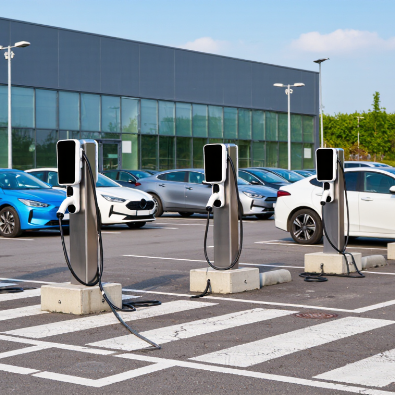
In 2026, the best EV charger pedestal for a parking lot should match vehicle demand, electrical capacity, and daily parking behavior. Level 2 charging remains practical for workplaces, apartments, hotels, and public lots. Each port can deliver 7.2–19.2 kW, depending on voltage, amperage, and equipment settings. That range is significant. A 7.2 kW port suits longer stays, while a 19.2 kW port can add energy faster during short visits.
A reliable installation begins with a verified electrical assessment. Technicians should check transformer capacity, panel space, feeder length, and voltage drop before selecting pedestal locations. Load management may prevent expensive service upgrades when several vehicles charge together. In the field, clear cable reach matters as much as power. A poorly placed pedestal can create stretched cables, blocked walkways, or awkward parking angles. Small details matter.
Concrete foundations should resist vehicle movement, standing water, and seasonal ground changes. Protective barriers can reduce impact damage, but they must not obstruct access routes. Weather-resistant enclosures, drainage planning, lighting, and visible instructions improve everyday use. Local electrical and accessibility requirements still need professional review. My own installation planning has sometimes focused too heavily on maximum power. That can be a mistake. Many drivers value dependable access more than peak charging speed, especially when vehicles remain parked for several hours. Performance should be measured after commissioning, not assumed from a specification sheet.
A reliable EV charger pedestal installation begins with a measured site assessment. The International Energy Agency reported nearly 14 million electric cars sold worldwide in 2023, representing about 18% of new car sales. Parking demand is growing quickly. Electrical planning cannot rely on visual panel space alone.
Apply NEC Article 625 during the assessment. Treat EV charging as a continuous load, then size feeders and branch circuits at 125% of the calculated charging current. Confirm whether the property provides 208Y/120 V three-phase power or 240 V single-phase service. They are not interchangeable for every charger. Record transformer capacity, panel ratings, available fault current, conductor length, voltage drop, and future load growth. A 48-ampere charger may require a 60-ampere branch circuit. Several pedestals can exceed a small commercial service surprisingly fast.
The U.S. Department of Energy’s Alternative Fueling Station data shows continuing expansion of public charging infrastructure, reinforcing the need for scalable electrical design. Specify copper or aluminum conductors according to ampacity, installation conditions, and local requirements. Protect outdoor equipment from impact, water, and vehicle movement. Keep conduit routes short and maintain clear pedestrian paths. Load management may reduce service upgrades, but it should be verified by calculations, not assumed. One weak point remains common: installers sometimes size for today’s chargers and forget tomorrow’s parking demand. That mistake is expensive to correct.
Site Assessment: Apply NEC 625 and Size 208/240 V Electrical Capacity
Planning basis: Level 2 EVSE rated at 32 A per port, with no load-management diversity applied. The design load applies a 125% continuous-load factor consistent with NEC 625 considerations. Confirm available utility capacity, feeder ampacity, overcurrent protection, voltage drop, grounding, and local requirements during the site assessment.
A successful 2026 EV charger pedestal installation starts with the parking stall, not the equipment. The layout must welcome drivers with different mobility needs. ADA access should connect clearly to the building entrance, curb ramp, and accessible route. Keep the access aisle level, unobstructed, and visibly marked.
For many sites, a 10–12-foot EV stall width gives drivers useful door clearance. It also leaves room for charging cables without blocking the neighboring vehicle. Place the pedestal near the stall edge, but keep its screen and connector within comfortable reach.
Avoid locating it beside drainage grates, wheel stops, or steep pavement transitions. Small obstacles become frustrating during rain, snow, or nighttime charging.
Field reviews often reveal a simple problem: the drawing looks spacious, but parked vehicles reduce the usable aisle. Check turning paths with a large vehicle before concrete work begins. Confirm local accessibility requirements with a qualified designer or authority. Rules can vary by location and site type.
Lighting should illuminate the pedestal, markings, and access path without creating harsh glare. Protective posts may prevent impact damage, yet they must not narrow the accessible route.
One detail is easy to miss. Cable storage needs a defined position, or it may cross the aisle.
A practical design leaves room for imperfect parking, because drivers rarely stop exactly on the lines.
Parking demand is rising with EV adoption. The International Energy Agency reported over 17 million electric car sales worldwide in 2024, exceeding one-fifth of new car sales. Parking facilities now need electrical planning, not only attractive pedestals. Each EV charger should be treated as a continuous load under applicable electrical codes. In practice, the branch circuit must be sized at 125% of the charger’s maximum output.
Consider four 9.6 kW chargers on a 208-volt, three-phase system. Their combined continuous load is 38.4 kW. Applying the 125% rule produces a design load of 48 kW, or approximately 133 amperes. A 150-ampere circuit may appear adequate, but voltage drop, conductor temperature, conduit fill, and future expansion still require review. Small details matter.
The National Electrical Code, including Article 625 and continuous-load requirements, guides this calculation in the United States. Local authorities may apply additional requirements. A qualified electrical professional should verify service capacity, grounding, disconnect placement, and available fault current before installation. The U.S. Department of Energy’s Alternative Fuels Data Center also emphasizes proper site assessment for charging infrastructure. Load management can reduce simultaneous demand, but its controls must be listed, commissioned, and tested. I have seen designs rely on software assumptions too early. That is risky. A measured commissioning test, clear panel labeling, and thermal inspection provide stronger evidence than a spreadsheet alone.
A reliable public charging site begins with disciplined commissioning. Inspect each pedestal, cable, connector, breaker, network link, and payment interface before opening the parking lot. Confirm correct grounding and test emergency shutdown controls under supervised conditions. A qualified technician should record voltage, charging speed, error codes, and cabinet temperature. Photos of cable routing and access clearances create useful evidence for future service.
Targeting 97% or higher uptime requires more than replacing failed parts. Monitor every charger daily, including unavailable, offline, and derated states. Set alerts for repeated session failures, abnormal temperatures, and communication loss. Clean connectors and screens on a scheduled route. Check cooling paths after dusty or wet weather. Keep critical spare parts nearby, but do not store them without inspection. Batteries, seals, and cables can age quietly.
Our early maintenance plan focused on hardware failures. That assumption was wrong. Several interruptions came from network resets and unclear user instructions. Now, technicians review transaction logs and speak with parking staff after difficult incidents. A simple sign can prevent a stalled session. Measure uptime by charger and by hour, not only across the whole site. A monthly 98% result can hide one heavily used unit operating at 91%. Maintenance records should include response time, repair cause, restored time, and recurring patterns. Some faults still appear without warning. That is why honest reporting matters.
| Category | Performance Dimension | Recommended Target | Acceptance or Measurement Method | Review Frequency | Corrective Action Trigger |
|---|---|---|---|---|---|
| Installation and Commissioning | Pedestal foundation and anchoring | Stable, level, and resistant to movement, vibration, and water accumulation | Visual inspection; verify anchor installation, plumb alignment, drainage, and concrete condition against approved drawings | At installation and after severe weather | Any visible movement, cracking that affects stability, exposed anchor hardware, or persistent standing water |
| Electrical protection and grounding | Correct overcurrent protection, grounding, bonding, and residual-current protection for the site design | Electrical test records, protective-device verification, torque checks, and comparison with approved single-line diagrams | Before energization and after electrical modifications | Failed protection test, missing bonding conductor, incorrect rating, overheating, or abnormal voltage drop | |
| Charging output and connector operation | Every connector completes a controlled charging session without interruption | Test with an approved vehicle or test load; verify start, stop, authorization, cable locking, and emergency-stop behavior | Commissioning and after major repair | Any failed session, connector lock failure, damaged cable, overheating, or repeated communication error | |
| Network, payment, and backend communication | Successful authorization, transaction reporting, status updates, and remote control | Complete test transactions and confirm charger status, energy data, alarms, and session records reach the management platform | Commissioning and monthly review | Offline status lasting more than 15 minutes, missing transaction data, or unsuccessful payment authorization | |
| Accessibility, signage, lighting, and parking layout | Clear access, visible instructions, unobstructed charging spaces, and safe pedestrian movement | Site walkthrough during daytime and nighttime; verify signs, lighting, bollards, cable reach, and accessible route requirements | Commissioning, quarterly, and after site changes | Blocked access, damaged signage, inadequate illumination, trip hazard, or unsafe cable placement | |
| Maintenance and Uptime Control | Public charger uptime | 97% or higher per calendar month | Uptime = available connector-hours divided by scheduled connector-hours, excluding documented utility outages and approved planned maintenance | Monthly | Monthly uptime below 97%, repeated failures at the same location, or unexplained data gaps |
| Critical incident response | Remote acknowledgement within 15 minutes; dispatch decision within 60 minutes | Measure elapsed time from alarm receipt to ticket acknowledgement and field-service decision | Each incident; summarized monthly | Missed response target, safety-related alarm, full-site outage, or payment-system failure | |
| Mean time to repair | Restore critical charging service within 24 hours where parts and site access are available | Measure time from confirmed failure to verified return to service | Each incident; monthly trend review | Repair exceeds 24 hours, repeat service call within 30 days, or unresolved safety defect | |
| Preventive inspection completion | 100% of scheduled inspections completed within the maintenance window | Review service records for connector condition, cable insulation, enclosure seals, filters, fasteners, displays, and emergency controls | Monthly or according to site risk assessment | Missed inspection, incomplete checklist, water ingress, corrosion, or damaged user-contact components | |
| Firmware, cybersecurity, and configuration control | Approved updates applied with rollback and recovery procedures documented | Maintain asset inventory, version records, access controls, backup configuration, and post-update functional tests | Monthly review and after every update | Unsupported software, unapproved configuration change, failed update, exposed credentials, or missing audit record | |
| Reporting and Optimization | Energy delivery and session success rate | At least 98% of valid charging attempts start successfully, excluding user cancellation and vehicle-side faults | Compare completed, failed, cancelled, and vehicle-rejected sessions using backend records and incident logs | Monthly | Success rate below target or three similar failures within seven days |
| Spare parts and critical equipment availability | Maintain serviceable replacement parts for common failure items and site-specific components | Review stock list, lead times, part condition, and minimum reorder levels | Monthly and after major repair | No replacement available for a recurring failure or repair delayed by preventable stockout | |
| Quarterly performance review | Sustained uptime of 97% or higher with documented improvement actions | Review uptime, downtime causes, repair time, energy delivery, complaints, safety events, and repeat failures | Quarterly | Negative three-month trend, unresolved root cause, or recurring downtime concentrated at one site |
Each port typically delivers 7.2–19.2 kW, depending on voltage, amperage, and equipment settings.
Review transformer capacity, panel space, feeder length, voltage drop, and future electrical demand. Visual panel space can mislead. Measured data matters more.
Load management can balance charging demand and reduce unnecessary service upgrades. Confirm its performance through calculations. Do not assume it will work.
A 48-ampere charger may need a 60-ampere branch circuit under continuous-load requirements. Qualified electrical professionals should verify the final design.
A 10–12-foot stall often provides better door clearance and cable movement. It also helps reduce contact with neighboring vehicles.
Place it near the stall edge, with the screen and connector within comfortable reach. Avoid drainage grates, wheel stops, and steep pavement transitions. Small obstacles become serious during rain.
Connect accessible spaces clearly to the entrance, curb ramp, and accessible route. Keep the access aisle level, marked, and unobstructed. Protective posts must not narrow the route.
Use foundations that resist vehicle movement, standing water, and seasonal ground changes. Weather-resistant enclosures, drainage, lighting, and visible instructions improve daily use.
A defined cable position prevents connectors from crossing walkways or blocking nearby vehicles. Cable reach matters greatly. I have focused too heavily on maximum power before, which was a mistake.
Planning the best EV charger pedestal parking lot installation begins with understanding Level 2 charging, which typically delivers 7.2–19.2 kW per port. A successful project starts with a site assessment covering parking flow, trenching, drainage, lighting, utility access, and future expansion. Electrical planning should follow NEC 625 requirements while confirming that the available 208/240 V service can support the expected charging load. Designers should also provide ADA-accessible routes, appropriate signage, and EV stall widths of approximately 10–12 feet to improve safety and usability.
Knowing how to install an ev charger pedestal in a parking lot requires careful coordination between civil, electrical, and operational work. Installers should select suitable foundations, protect conduits, balance circuits, and size each continuous-load circuit at 125% of the calculated demand. After installation, commissioning should verify voltage, communication, charging performance, safety protections, and payment or access functions. A preventive maintenance plan, remote monitoring, prompt repairs, and periodic inspections can help public chargers achieve a target uptime of 97% or higher.

Midwest Charger